Introduction

Principle & Structure
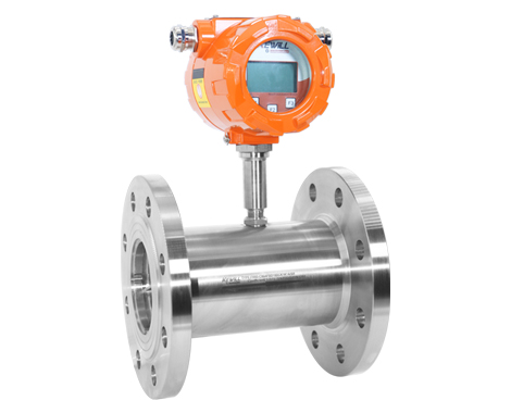
Turbine flowmeters are a type of velocity flowmeter. As shown in the figure below, a turbine is placed in the center of the pipeline, and the two ends are supported by bearings. When the fluid passes through the pipeline, it impacts the turbine blades and generates a driving torque for the turbine, so that the turbine can overcome the friction torque and fluid resistance torque and generate rotation. Within the flow range, for a certain viscosity of the fluid medium, the rotational angular velocity of the turbine is proportional to the fluid velocity. Thus, the fluid velocity can be obtained from the rotational angular velocity of the turbine, so that the fluid flow through the pipeline can be calculated.

The rotational speed of the turbine is detected by a sensing coil installed outside the casing. When the turbine blades cut the magnetic field lines generated by the permanent magnet steel in the casing, it will cause a change in the magnetic flux in the sensing coil. The sensing coil will detect The magnetic flux cycle change signal is sent to the preamplifier, which amplifies and shapes the signal to generate a pulse signal proportional to the flow rate, which is sent to the unit conversion and flow accumulation circuit to obtain and display the cumulative flow value; at the same time, the pulse signal is also sent to the The frequency current conversion circuit converts the pulse signal into an analog current, and then indicates the instantaneous flow value.

Features

● Installed with high-reliability long-life bearings

● Excellent repeatability, suitable for batching

● Excellent low flow rate measurement performance

● Extremely fast response, suitable for batch control and proportioning control applications

● Rotor with multi-blade structure, high precision

● Steam cleaning allowed

● With high and low alarm function, can drive relay

● With 10-point nonlinear correction function

● Standard RS485 communication (MODBUS protocol)

● Modular circuit design and rich self-diagnosis function, easy maintenance

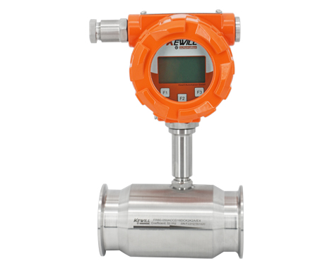
● The compact type is suitable for equipment installation

application

● Refined oil, light crude oil, gasoline, light oil, jet fuel, light diesel oil, naphtha, ethylene, etc.

● Lubricating oil, hydraulic oil, etc.

● Water, pure water, distilled water, deionized water, desalinated water, demineralized water, etc.

● Alcohol, benzene, toluene, xylene, butadiene, carbon tetrachloride, methylamine, acrylonitrile, etc.

● Formaldehyde, acid, caustic soda, carbon disulfide, etc.

● Milk, coffee, etc.

● High temperature medium such as heat transfer oil and hot kerosene

technical parameter

Performance parameters
Accuracy:0.5% of rate and 0.2% of rate
Repeatability:±0.1% of measured value
Response time:50 ms max relative to input change
stability:Stability over 6 months is ±0.1% of measured value
Influence of ambient temperature:Over the operating temperature range is ±0.25%
Influence of installation location:Can ensure that the sensor is full of pipes and ensure enough straight pipe sections before and after, the installation has no effect
Start Time:50ms from zero traffic
Preheat time:It takes 5 minutes from power transmission to the rated measurement accuracy
Sensor parameters
size:DN4 to DN250
Measured fluid temperature range:-29 to 120℃; -29 to 300℃ (high temperature customized type)
Sensor body material:AISI 304 SST, optional 316L
Impeller and accessories material:AISI 304 SST, optional 316L
Ball bearing material:316L SST bearing or ceramic bearing
Process connection:DIN PN10 to PN63
Coil Impedance:1600 ohm
Converter parameters
Ambient temperature range:-20 to 140° F (-29 to 60 ℃ )
Converter housing material:Low copper die-cast aluminum Nema 4X, IEC60529 IP66 (standard), customizable stainless steel converter housing
Converter seal:rubber
power supply:AC 86 to 265V, 50/60HZ, 1A fast blow fuse; DC 16.8V to 31.2V, 1A fast blow fuse; or 3.6V battery powered
Protocol:RS485 communication (MODBUS protocol)
Protection class:IP65&IP68
Electrical Interface:2 PG13.5
power:3W
output:4 to 20 mA current output (for instantaneous flow), pulse output (for total amount)
With high alarm and low alarm output, two groups of normally open contacts, driving capacity: 24VDC, 30mA

Selection table

FR80-Turbine Flowmeter
               The way to

DN4 DN6 DN10 DN15 DN20 DN25 DN32 DN40 DN50 DN65 DN80 DN100 DN125 DN150 DN200 DN250 (Special diameters such as DN300 are delivered by agreement)
               output signal

Pulse +4 to 20mA current signal

Pulse +0 to 5V voltage signal

High point and low point normally open contact signal (full-scale switch value setting)
         Connection method

Threaded seal connection

Flange connection

Sanitary clamp connection

Quick Seal Hose Fittings
         precision

Accuracy 0.2% (applicable to pipes above DN15)

Accuracy 0.5% (applicable to pipes above DN10)

Accuracy 1.0
         Pressure rating

EN 1092-1 (DIN) PN10
ASME B16.5(ANSI)CLASS150

EN 1092-1 (DIN) PN16
ASME B16.5(ANSI)CLASS300

EN 1092-1 (DIN) PN25
ASME B16.5(ANSI)CLASS600

EN 1092-1 (DIN) PN40
ASME B16.5(ANSI)CLASS900

EN 1092-1 (DIN) PN63
ASME B16.5(ANSI)CLASS1500

EN 1092-1 (DIN) PN100
ASME B16.5(ANSI)CLASS2500

EN 1092-1 (DIN) PN250
HE IS 10K

EN 1092-1 (DIN) PN400
HE IS 20K

Product application specific standards

          System power supply

12 to 24V DC

86 to 265V AC

3.6V lithium battery (only for pulse signal or display selection)

Wetted body material

Stainless steel 1.4301(304)

Stainless steel 1.4435 (316L)

Internal Impeller and Attachment Material

403F stainless steel

Stainless steel 1.4435 (316L)

Hastelloy C

Bearing material

Stainless Steel 440C Ball Bearings (Non-Water Environment)

Ceramic journal bearings

Graphite journal bearings

Tungsten Carbide Journal Bearings

(special option) VARIO
         Customized with special parameters
The complete data of this selection table, please contact the sales staff or email to sales@kewill-auto.cn for complete samples.
Prev :FR60 Series Turbine Flow Meters (Compact)
Next:No